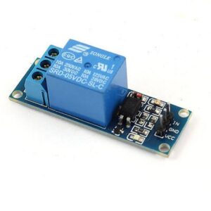
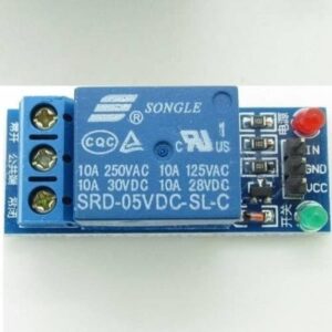
1 Channel Relay Board 5V with Optocoupler
1. Channel – 1
2. Trigger Voltage (VDC) – 5
3. Switching Voltage (VAC) – 250@10A
4. Switching Voltage (VDC) – 30@10A
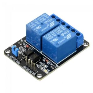
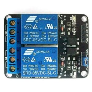
2 Channel Relay Board 5V
1. No. of Channel: 2
2. Trigger Voltage: 5VDC
3. Triode drive, increasing relay coil
4. High impedance controller pin
5. Pull-down circuit for the avoidance of malfunction
6. Power supply indicator and Control indicator lamp
7. Power supply and relay instructions, lit, the disconnect is off;
8. The input signal, signal, common Terminal and start conducting;
4 Channel Relay Board 5V
1. No. of Channel: 4
2. Trigger Voltage: 5VDC
3. Triode drive, increasing relay coil
4. High impedance controller pin
5. Pull-down circuit for the avoidance of malfunction
6. Power supply indicator and Control indicator lamp
7. Power supply and relay instructions, lit, the disconnect is off;
8. The input signal, signal, common Terminal and start conducting;
8 Channel Relay Board 5V
1. Channel: 8 channel
2. Relay Operating Voltage: 5V
3. One normally closed contact and one normally open contact
4. Triode drive, increasing relay coil
5. High impedance controller pin
6. Pull-down circuit for the avoidance of malfunction
7. Power supply indicator and Control indicator lamp
8. Power supply and relay instructions, lit, the disconnect is off;
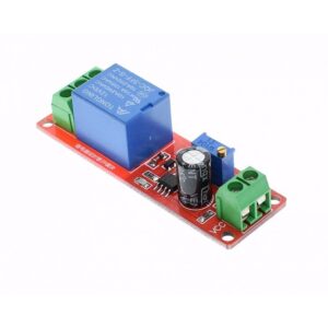
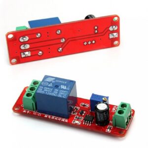
NE555 Timer Switch Adjustable Relay Board
1. Module based on the NE555 chip.
2. Input voltage: DC 12V
3. Adjustable time: 0-10 s
4. AC Control voltage: 250V/max. 10A
5. Max. load: 2200W


